

#include "utility/Adafruit_MS_PWMServoDriver.h"Īdafruit_MotorShield AFMS = Adafruit_MotorShield() Īdafruit_StepperMotor *myMotor1 = AFMS.getStepper(200, 1) Īdafruit_StepperMotor *myMotor2 = AFMS.GAF Indie Steam Group (We are currently looking for someone to handle the Steam Group announcements, any volunteers are welcome to contact me via PM): To learn the basics of stepper motor and its connection to Arduino UNO R3, please refer back to Using Arduino with Parts and Sensors – Stepper Motor Part 1 Just follow the instruction to connect the wires from motors. The beauty of this stepper motor shield is that it does not use any pin in Arduino because it is connected through I2C. This motor shield is capable of running 2 stepper motors and 2 servos.
#PARALAX GROWBOT INSTALL#
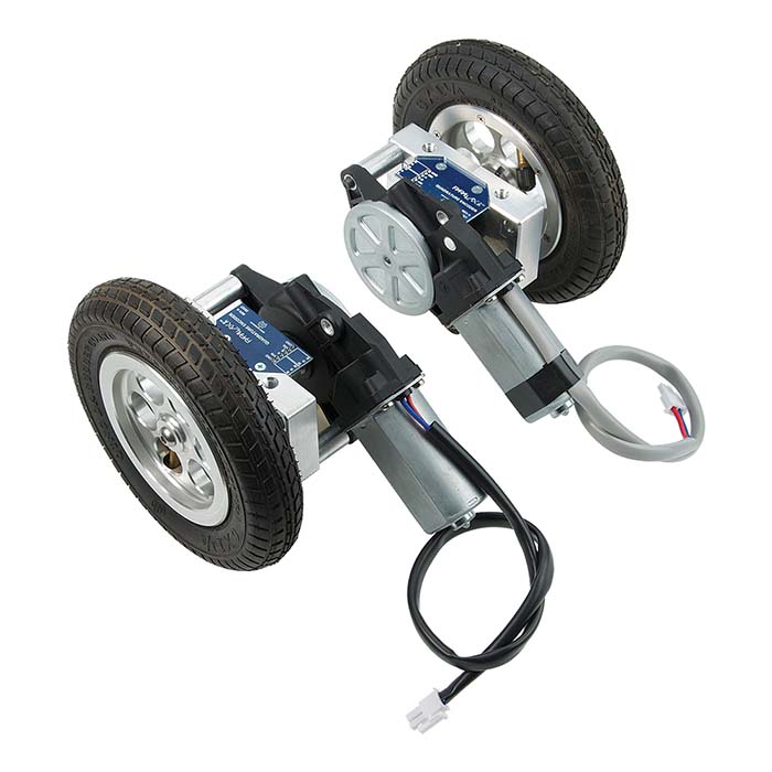
To install motors we need 6.5 cm x 4.5 cm acrylics for mounting motor into the chassis as shown in Figure 1. We’re using NEMA 17 stepper motor, which h as a resolution of 200 steps/revolution. It is specifically designed for servo instead of stepper motor, so we need to make a little modification to the design.įirst, we will cut the lower part of both sides of the chassis to save space for motor attachment. The chassis from Parallax is made from strong aluminium. Install motors, wheels, and the acrylic base Lipo battery 3s (11.1V) and Connectors ( ).Adafruit Motor Stepper Shield for Arduino (.The hardware required for this robot are available in many electronics shops, we provide examples of shops in the Hardware list. By doing this approach, if any problem occurs, it will be easier to fix. Then, in the next article we will add on the rest of the devices one by one, followed by programs to test correct installation and connection.
#PARALAX GROWBOT SOFTWARE#
Then a small program was shown to test the motors to ensure proper connections and software installation. We will discuss the building of this Arduino robot step by step, first step is the basic installation of the chassis, motors and Arduino/motor shield. We’ll use stepper motor for smooth, quiet operation. The distance measured is then displayed on a small OLED. The sensor is attached to a servo so the robot can pan left and right to take several measurements. Make decision on which direction it will take (forward, backward, left or right) based on the longest distance available.Measure distance from various directions (forward, 90 degree left & right, 45 degree left & right.Avoid obstacles by moving in different directions based on best available paths.Move forward, backward, turn 90 degree left & right and turn 45 degree left & right.It’ll be able to detect and avoid obstacles as they roam around. This Arduino robot is designed to be autonomous. The laser sensor will allow us to obtain more accurate and reliable data. In this article, we will further improve the functionality of the robot by making it mobile and adding laser range finder (LRF) to allow the robot to detect objects and measure distances.
#PARALAX GROWBOT HOW TO#
In the previous posts, How To Make Your Own Robot and How To Make Your Own Robot (Part 2), we showed a simple way to build your own robot from scratch using Arduino UNO R3. Well, this Parallax laser Arduino robot would come in very handy! You need furniture ASAP but you don’t have measure tape with you. Imagine you’ve just moved into a new place.


 0 kommentar(er)
